VORSICHTSMASSNAHMEN BEI ARBEITEN AM SRS
Fahrzeugdaten
Gefahr
Um Verletzungen bei Ihnen oder anderen Personen durch unbeabsichtigtes Auslösen des Airbags während der Wartungsarbeiten zu vermeiden, lesen und befolgen Sie sorgfältig alle in diesem Handbuch beschriebenen Vorsichtsmaßnahmen und Verfahren.
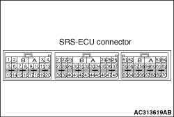
Vorsicht Versuchen Sie nicht, die Kabelbaumstecker des SRS zu reparieren. Wird ein defekter Kabelbaum festgestellt, ist dieser gemäß der nachstehenden Tabelle instand zu setzen oder zu ersetzen. Klemmen-Nr. der SRS-ECU Ziel des Kabelbaums Abhilfemaßnahme 5, 6 Bodenkabelbaum (LH) → Kopfairbagmodul (LH) Bodenkabelbaum instand setzen oder ersetzen. 7, 8 Bodenkabelbaum (LH) → Gurtstraffer (LH) Bodenkabelbaum instand setzen oder ersetzen. 9, 10 Bodenkabelbaum (LH) → Seitenairbagmodul (LH) Bodenkabelbaum instand setzen oder ersetzen. 15, 16 Bodenkabelbaum (LH) → Seitenaufprallsensor (hinten) (LH) Bodenkabelbaum instand setzen oder ersetzen. 19, 20 Bodenkabelbaum (LH) → Seitenaufprallsensor (vorn) (LH) Bodenkabelbaum instand setzen oder ersetzen. 21 Instrumententafel-Kabelbaum → Anzeigeleuchte „Beifahrerairbag AUS“ Instrumententafel-Kabelbaum instand setzen oder ersetzen. 23 Instrumententafel-Kabelbaum → Anschlussblock (Sicherung No.3) Instrumententafel-Kabelbaum instand setzen oder ersetzen. 24 Instrumententafel-Kabelbaum → Anschlussblock (Sicherung No.2) Instrumententafel-Kabelbaum instand setzen oder ersetzen. 27, 28 Instrumententafel-Kabelbaum → Beifahrerairbagmodul (vorn), Seite des 1. Zünders Instrumententafel-Kabelbaum instand setzen oder ersetzen. 29 Instrumententafel-Kabelbaum → Anschluss ON des Beifahrerairbag-Abschalters Instrumententafel-Kabelbaum instand setzen oder ersetzen. 30, 31 Instrumententafel-Kabelbaum → Beifahrerairbagmodul (vorn), Seite des 2. Zünders Instrumententafel-Kabelbaum instand setzen oder ersetzen. 32 Instrumententafel-Kabelbaum → Can_H-Leitung CAN-Leitung instand setzen oder ersetzen. 33, 34 Instrumententafel-Kabelbaum → Wickelfeder → Fahrerairbagmodul, Seite des 2. Zünders Instrumententafel-Kabelbaum instand setzen oder ersetzen. Wickelfeder ersetzen. 35 Instrumententafel-Kabelbaum → gemeinsamer Anschluss des Beifahrerairbag-Abschalters Instrumententafel-Kabelbaum instand setzen oder ersetzen. 36, 37 Instrumententafel-Kabelbaum → Wickelfeder → Fahrerairbagmodul, Seite des 1. Zünders Instrumententafel-Kabelbaum instand setzen oder ersetzen. Wickelfeder ersetzen. 38, 39 Instrumententafel-Kabelbaum → vorderer Kabelbaum → Frontaufprallsensor (LH) Jeden Kabelbaum instand setzen oder ersetzen. 40 Instrumententafel-Kabelbaum→ Masse Instrumententafel-Kabelbaum instand setzen oder ersetzen. 41 Instrumententafel-Kabelbaum → Anschluss OFF des Beifahrerairbag-Abschalters Instrumententafel-Kabelbaum instand setzen oder ersetzen. 43 Instrumententafel-Kabelbaum → Can_L-Leitung CAN-Leitung instand setzen oder ersetzen. 47, 48 Instrumententafel-Kabelbaum → Steuerkabelbaum → Frontaufprallsensor (RH) Jeden Kabelbaum instand setzen oder ersetzen. 57, 58 Bodenkabelbaum (LH) → Bodenkabelbaum (RH) → Seitenairbagmodul (RH) Jeden Kabelbaum instand setzen oder ersetzen. 59, 60 Bodenkabelbaum (LH) → Bodenkabelbaum (RH) → Gurtstraffer (RH) Jeden Kabelbaum instand setzen oder ersetzen. 61, 62 Bodenkabelbaum (LH) → Bodenkabelbaum (RH) → Kopfairbagmodul (RH) Jeden Kabelbaum instand setzen oder ersetzen. 63, 64 Bodenkabelbaum (LH) → Bodenkabelbaum (RH) → Seitenaufprallsensor (vorn) (RH) Jeden Kabelbaum instand setzen oder ersetzen. 67, 68 Bodenkabelbaum (LH) → Bodenkabelbaum (RH) → Seitenaufprallsensor (hinten) (RH) Jeden Kabelbaum instand setzen oder ersetzen.
Klemmen-Nr. der SRS-ECU
Ziel des Kabelbaums
Abhilfemaßnahme
5, 6
Bodenkabelbaum (LH) → Kopfairbagmodul (LH)
Bodenkabelbaum instand setzen oder ersetzen.
7, 8
Bodenkabelbaum (LH) → Gurtstraffer (LH)
Bodenkabelbaum instand setzen oder ersetzen.
9, 10
Bodenkabelbaum (LH) → Seitenairbagmodul (LH)
Bodenkabelbaum instand setzen oder ersetzen.
15, 16
Bodenkabelbaum (LH) → Seitenaufprallsensor (hinten) (LH)
Bodenkabelbaum instand setzen oder ersetzen.
19, 20
Bodenkabelbaum (LH) → Seitenaufprallsensor (vorn) (LH)
Bodenkabelbaum instand setzen oder ersetzen.
- Instrumententafel-Kabelbaum → Anzeigeleuchte „Beifahrerairbag AUS“ Instrumententafel-Kabelbaum instand setzen oder ersetzen.
- Instrumententafel-Kabelbaum → Anschlussblock (Sicherung No.3) Instrumententafel-Kabelbaum instand setzen oder ersetzen.
- Instrumententafel-Kabelbaum → Anschlussblock (Sicherung No.2) Instrumententafel-Kabelbaum instand setzen oder ersetzen.
27, 28
Instrumententafel-Kabelbaum → Zünderseite 1 des Beifahrerairbag-Moduls (vorn)
Instrumententafel-Kabelbaum instand setzen oder ersetzen.
- Instrumententafel-Kabelbaum → Anschluss ON des Beifahrerairbag-Deaktivierungsschalters Instrumententafel-Kabelbaum instand setzen oder ersetzen.
30, 31
Instrumententafel-Kabelbaum → Zünderseite 2 des Beifahrerairbag-Moduls (vorn)
Instrumententafel-Kabelbaum instand setzen oder ersetzen.
- Instrumententafel-Kabelbaum → Can_H-Leitung CAN-Leitung instand setzen oder austauschen.
33, 34
Instrumententafel-Kabelbaum → Kontaktspirale → Zünderseite 2 des Fahrerairbag-Moduls
Instrumententafel-Kabelbaum instand setzen oder austauschen. Kontaktspirale austauschen.
- Instrumententafel-Kabelbaum → gemeinsamer Anschluss des Beifahrerairbag-Deaktivierungsschalters Instrumententafel-Kabelbaum instand setzen oder ersetzen.
36, 37
Instrumententafel-Kabelbaum → Kontaktspirale → Zünderseite 1 des Fahrerairbag-Moduls
Instrumententafel-Kabelbaum instand setzen oder austauschen. Kontaktspirale austauschen.
38, 39
Instrumententafel-Kabelbaum → vorderer Kabelbaum → Frontaufprallsensor (LH)
Jeden Kabelbaum instand setzen oder austauschen.
- Instrumententafel-Kabelbaum → Masse Instrumententafel-Kabelbaum instand setzen oder ersetzen.
- Instrumententafel-Kabelbaum → Anschluss OFF des Beifahrerairbag-Deaktivierungsschalters Instrumententafel-Kabelbaum instand setzen oder ersetzen.
- Instrumententafel-Kabelbaum → Can_L-Leitung CAN-Leitung instand setzen oder austauschen.
47, 48
Instrumententafel-Kabelbaum → Steuerkabelbaum → Frontaufprallsensor (RH)
Jeden Kabelbaum instand setzen oder austauschen.
57, 58
Bodenkabelbaum (LH) → Bodenkabelbaum (RH) → Seitenairbag-Modul (RH)
Jeden Kabelbaum instand setzen oder austauschen.
59, 60
Bodenkabelbaum (LH) → Bodenkabelbaum (RH) → Sicherheitsgurtstraffer (RH)
Jeden Kabelbaum instand setzen oder austauschen.
61, 62
Boden-Kabelbaum (LH) → Boden-Kabelbaum (RH) → Kopfairbagmodul (RH)
Jeden Kabelbaum instand setzen oder austauschen.
63, 64
Boden-Kabelbaum (LH) → Boden-Kabelbaum (RH) → Seitenaufprallsensor (vorn) (RH)
Jeden Kabelbaum instand setzen oder austauschen.
67, 68
Boden-Kabelbaum (LH) → Boden-Kabelbaum (RH) → Seitenaufprallsensor (hinten) (RH)
Jeden Kabelbaum instand setzen oder austauschen.
Gefahr
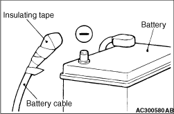
Nach dem Abklemmen des Batteriekabels mindestens 60 Sekunden warten, bevor mit den folgenden Arbeiten begonnen wird. Zusätzlich den Minuspol der Batterie mit Klebeband isolieren. Der Kondensator in der SRS-ECU ist so ausgelegt, dass er auch nach dem Abklemmen der Batterie kurzzeitig eine für die Auslösung des Airbags ausreichende Spannung speichert. Werden unmittelbar nach dem Abklemmen der Batteriekabel Arbeiten am SRS-System durchgeführt, kann eine unbeabsichtigte Auslösung des Airbags daher zu schweren Verletzungen führen.
Englisches Original anzeigen
SRS SERVICE PRECAUTIONS
danger In order to avoid injury to yourself or others from accidental deployment of the air bag during servicing, read and carefully follow all the precautions and procedures described in this manual.
danger
In order to avoid injury to yourself or others from accidental deployment of the air bag during servicing, read and carefully follow all the precautions and procedures described in this manual.
caution Do not use any electrical test equipment on or near SRS components, except those specified on . Never Attempt to Repair the Following Components: SRS air bag control unit (SRS-ECU) Clock spring Driver’s and passenger’s (front) air bag modules Side-airbag module Curtain air bag module Front impact sensor Side impact sensors Passenger’s air bag cut off switch Seat belt with pre-tensioner
note If any of these components are diagnosed as faulty, they should only be replaced, in accordance with the INDIVIDUAL COMPONENTS SERVICE procedures in this manual, starting at page .
caution Do not attempt to repair the wiring harness connectors of the SRS. If a defective wiring harness is found, repair or replace it by referring to the table below. SRS-ECU terminal No. Destination of harness Remedy 5, 6 Floor wiring harness (LH) → Curtain air bag module (LH) Correct or replace floor wiring harness. 7, 8 Floor wiring harness (LH) → Seat belt pre-tensioner (LH) Correct or replace the floor wiring harness. 9, 10 Floor wiring harness (LH) → Side-airbag module (LH) Correct or replace the floor wiring harness. 15, 16 Floor wiring harness (LH) → Side impact sensor (rear) (LH) Correct or replace the floor wiring harness. 19, 20 Floor wiring harness (LH) → Side impact sensor (front) (LH) Correct or replace the floor wiring harness. 21 Instrument panel wiring harness → Passenger’s air bag off indicator lamp Correct or replace the instrument panel wiring harness. 23 Instrument panel wiring harness → Junction block (fuse No.3) Correct or replace the instrument panel wiring harness. 24 Instrument panel wiring harness → Junction block (fuse No.2) Correct or replace the instrument panel wiring harness. 27, 28 Instrument panel wiring harness → Passenger’s (front) air bag module 1st squib side Correct or replace the instrument panel wiring harness. 29 Instrument panel wiring harness → Passenger’s air bag cut off switch ON terminal Correct or replace the instrument panel wiring harness. 30, 31 Instrument panel wiring harness → Passenger’s (front) air bag module 2nd squib side Correct or replace the instrument panel wiring harness. 32 Instrument panel wiring harness → Can_H line Correct or replace the can line. 33, 34 Instrument panel wiring harness → Clock spring → Driver’s air bag module 2nd squib side Correct or replace instrument panel wiring harness. Replace the clock spring. 35 Instrument panel wiring harness → Passenger’s air bag cut off switch common terminal Correct or replace the instrument panel wiring harness. 36, 37 Instrument panel wiring harness → Clock spring → Driver’s air bag module 1st squib side Correct or replace instrument panel wiring harness. Replace the clock spring. 38, 39 Instrument panel wiring harness → Front wiring harness → Front impact sensor (LH) Correct or replace each wiring harness. 40 Instrument panel wiring harness→ Earth Correct or replace the instrument panel wiring harness. 41 Instrument panel wiring harness → Passenger’s air bag cut off switch OFF terminal Correct or replace the instrument panel wiring harness. 43 Instrument panel wiring harness → Can_L line Correct or replace the can line. 47, 48 Instrument panel wiring harness → Control wiring harness → Front impact sensor (RH) Correct or replace each wiring harness. 57, 58 Floor wiring harness (LH) → Floor wiring harness (RH) → Side-airbag module (RH) Correct or replace each wiring harness. 59, 60 Floor wiring harness (LH) → Floor wiring harness (RH) → Seat belt pre-tensioner (RH) Correct or replace each wiring harness. 61, 62 Floor wiring harness (LH) → Floor wiring harness (RH) → Curtain air bag module (RH) Correct or replace each wiring harness. 63, 64 Floor wiring harness (LH) → Floor wiring harness (RH) → Side impact sensor (front) (RH) Correct or replace each wiring harness. 67, 68 Floor wiring harness (LH) → Floor wiring harness (RH) → Side impact sensor (rear) (RH) Correct or replace each wiring harness.
SRS-ECU terminal No.
Destination of harness
Remedy
5, 6
Floor wiring harness (LH) → Curtain air bag module (LH)
Correct or replace floor wiring harness.
7, 8
Floor wiring harness (LH) → Seat belt pre-tensioner (LH)
Correct or replace the floor wiring harness.
9, 10
Floor wiring harness (LH) → Side-airbag module (LH)
Correct or replace the floor wiring harness.
15, 16
Floor wiring harness (LH) → Side impact sensor (rear) (LH)
Correct or replace the floor wiring harness.
19, 20
Floor wiring harness (LH) → Side impact sensor (front) (LH)
Correct or replace the floor wiring harness.
- Instrument panel wiring harness → Passenger’s air bag off indicator lamp Correct or replace the instrument panel wiring harness.
- Instrument panel wiring harness → Junction block (fuse No.3) Correct or replace the instrument panel wiring harness.
- Instrument panel wiring harness → Junction block (fuse No.2) Correct or replace the instrument panel wiring harness.
27, 28
Instrument panel wiring harness → Passenger’s (front) air bag module 1st squib side
Correct or replace the instrument panel wiring harness.
- Instrument panel wiring harness → Passenger’s air bag cut off switch ON terminal Correct or replace the instrument panel wiring harness.
30, 31
Instrument panel wiring harness → Passenger’s (front) air bag module 2nd squib side
Correct or replace the instrument panel wiring harness.
- Instrument panel wiring harness → Can_H line Correct or replace the can line.
33, 34
Instrument panel wiring harness → Clock spring → Driver’s air bag module 2nd squib side
Correct or replace instrument panel wiring harness. Replace the clock spring.
- Instrument panel wiring harness → Passenger’s air bag cut off switch common terminal Correct or replace the instrument panel wiring harness.
36, 37
Instrument panel wiring harness → Clock spring → Driver’s air bag module 1st squib side
Correct or replace instrument panel wiring harness. Replace the clock spring.
38, 39
Instrument panel wiring harness → Front wiring harness → Front impact sensor (LH)
Correct or replace each wiring harness.
- Instrument panel wiring harness→ Earth Correct or replace the instrument panel wiring harness.
- Instrument panel wiring harness → Passenger’s air bag cut off switch OFF terminal Correct or replace the instrument panel wiring harness.
- Instrument panel wiring harness → Can_L line Correct or replace the can line.
47, 48
Instrument panel wiring harness → Control wiring harness → Front impact sensor (RH)
Correct or replace each wiring harness.
57, 58
Floor wiring harness (LH) → Floor wiring harness (RH) → Side-airbag module (RH)
Correct or replace each wiring harness.
59, 60
Floor wiring harness (LH) → Floor wiring harness (RH) → Seat belt pre-tensioner (RH)
Correct or replace each wiring harness.
61, 62
Floor wiring harness (LH) → Floor wiring harness (RH) → Curtain air bag module (RH)
Correct or replace each wiring harness.
63, 64
Floor wiring harness (LH) → Floor wiring harness (RH) → Side impact sensor (front) (RH)
Correct or replace each wiring harness.
67, 68
Floor wiring harness (LH) → Floor wiring harness (RH) → Side impact sensor (rear) (RH)
Correct or replace each wiring harness.
danger After disconnecting the battery cable, wait 60 seconds or more before proceeding with the following work. In addition, insulate the negative battery terminal with a tape. The condenser inside the SRS-ECU is designed to retain enough voltage to deploy the air bag for a short time even after the battery has been disconnected, so serious injury may result from unintended air bag deployment if work is done on the SRS system immediately after the battery cables are disconnected.
danger
After disconnecting the battery cable, wait 60 seconds or more before proceeding with the following work. In addition, insulate the negative battery terminal with a tape. The condenser inside the SRS-ECU is designed to retain enough voltage to deploy the air bag for a short time even after the battery has been disconnected, so serious injury may result from unintended air bag deployment if work is done on the SRS system immediately after the battery cables are disconnected.
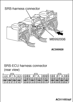
caution The SRS components and seat belt with pre-tensioner should not be subjected to heat, so remove the SRS-ECU, driver’s and passenger’s (front) air bag modules, clock spring, side-airbag modules, impact sensor, curtain air bag modules and seat belt pre-tensioner before drying or baking the vehicle after painting. SRS-ECU, air bag modules, clock spring, impact sensors: 93°C or more Seat belt with pre-tensioner: 90°C or more Whenever you finish servicing the SRS, always erase the diagnosis code and check warning lamp operation to make sure that the system functions properly. If checks are carried out by using the SRS-ECU harness connector, observe the following procedures: Insert the special tool extra fine probe (MB992006) into connector from harness side (rear side), and connect the tester to this probe. If any tool than special tool is used, damage to the harness and other components will result. Never insert the probe directly to the terminals from the front of the connector. The terminals are plated to increase their conductivity, so that if they are touched directly by the probe, the plating may break, which will cause drops in reliability.
Passende Ersatzteile
Für fahrzeugspezifische Teilenummern zuerst ein Fahrzeug im Konto auswählen.
Passende Handbuchstellen
Keine passende Handbuchstelle gefunden.
Kommentare
Kommentare werden geladen …
Registrieren oder anmelden, um zu kommentieren