DIAGNOSEFUNKTION
Fahrzeugdaten
Die Diagnosefunktion ruft mit dem M.U.T.-III Diagnosecodes und die Datenliste ab und ermöglicht die Durchführung des Stellgliedtests.
Diagnosecode Datenlistenausgabe Stellgliedtest Löschen von Diagnosecodes mit dem M.U.T.-III Freeze-Frame-Daten Statusanzeige nach Diagnosecode Anzeige der ECU-Informationen
ABLESEN VON DIAGNOSECODES
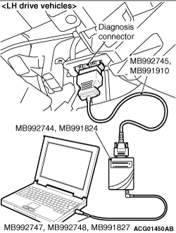
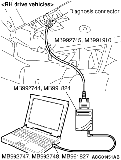
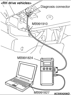
Das M.U.T.-III an den 16-poligen Diagnosestecker anschließen und den Diagnosecode ablesen. Hinweis Einzelheiten zur Verwendung des M.U.T.-III sind der „M.U.T.-III-Bedienungsanleitung“ zu entnehmen. Wenn bei Fahrzeugen mit Diebstahlalarmsensor das M.U.T.-III angeschlossen ist, der Zündschalter in die Stellung „ON“ gedreht und die geschlossene Motorhaube geöffnet wird, ertönt kurz die Sirene der Diebstahlwarnanlage. Dieses kurze Ertönen der Sirene der Diebstahlwarnanlage weist nicht auf eine Störung hin. Daher ist es zu ignorieren und die Diagnose mit dem M.U.T.-III durchzuführen. Sicherstellen, dass sich der Zündschalter in der Stellung „LOCK“ (OFF) befindet. Den Personal Computer starten. Das Spezialwerkzeug V.C.I.-Lite-USB-Kabel (MB992747/MB992748) oder M.U.T.-III-USB-Kabel (MB991827) an das V.C.I.-Lite (MB992744) bzw. V.C.I. (MB991824) und den Personal Computer anschließen. Den V.C.I.-Lite-Hauptkabelstrang A (MB992745) oder M.U.T.-III-Hauptkabelstrang A (MB991910) an das V.C.I.-Lite bzw. V.C.I. anschließen. Den V.C.I.-Lite-Hauptkabelstrang A oder M.U.T.-III-Hauptkabelstrang A an den Diagnosestecker des Fahrzeugs anschließen. Hinweis Wenn das V.C.I.-Lite an den Diagnosestecker angeschlossen ist, leuchtet die V.C.I.-Lite-Anzeigeleuchte grün. : Den V.C.I.-Netzschalter in die Stellung „ON“ drehen. Hinweis Wenn das V.C.I. mit Spannung versorgt wird, leuchtet die V.C.I.-Anzeigeleuchte grün. Das M.U.T.-III-System auf dem Personal Computer starten und den Zündschalter in die Stellung „ON“ drehen. Den Diagnosecode ablesen. Hinweis Beim Speichern des Diagnosecodes als Referenzinformation erfassen die Freeze-Frame-Daten die Daten zum Zeitpunkt der Bestätigung des Diagnosecodes und speichern anschließend den ECU-Status zu diesem Zeitpunkt. Durch die Analyse der einzelnen Daten mit dem M.U.T.-III kann die Fehlersuche effizient durchgeführt werden. Das Abklemmen des M.U.T.-III erfolgt in umgekehrter Reihenfolge des Anschlussvorgangs. Dabei sicherstellen, dass sich der Zündschalter in der Stellung „LOCK“ (OFF) befindet. Hinweis Die ABS-Warnleuchte kann blinken, wenn der Zündschalter bei angeschlossenem M.U.T.-III auf „ON“ gedreht wird. Dies ist darauf zurückzuführen, dass die Diagnoseanzeigefunktion der ABS-Warnleuchte durch Masseverbindung von Klemme No.1 des Diagnosesteckers aktiviert wird, und hat keinerlei nachteilige Auswirkungen.
LÖSCHEN VON DIAGNOSECODES (MIT DEM M.U.T.-III)
Das M.U.T.-III an den Diagnosestecker anschließen und den Diagnosecode löschen. Das Verfahren entspricht dem unter „ABLESEN VON DIAGNOSECODES“.
LÖSCHEN VON DIAGNOSECODES (OHNE M.U.T.-III)
1.Den Zündschalter in die Stellung „LOCK“ (OFF) drehen.
2.Das Minuskabel der Batterie abklemmen, mindestens 10 Minuten warten und anschließend wieder anklemmen.
3.Den Motor starten und 10 Minuten im Leerlauf laufen lassen.
ANSCHLIESSEN DES SWS-MONITORS
ANSCHLIESSEN DES SWS-KOMMUNIKATIONSLEITUNGS-SPEZIALWERKZEUGS SWS-MONITORKABELSTRANG (FÜR LENKSÄULEN-ECU) MB991812
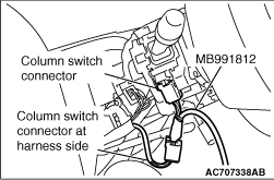
1.Die Lenksäulenabdeckung ausbauen.2.Den Steckverbinder des Lenksäulenschalters abziehen.3.Das Spezialwerkzeug SWS-Monitorkabelstrang (für Lenksäulen-ECU) MB991812 anschließen.
BEIM ANSCHLIESSEN DES DIAGNOSESTECKERS MIT DEN ZWISCHENLEITUNGEN FÜR DIE SWS-MONITOR-ANPASSUNG
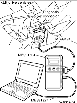
1.Das Spezialwerkzeug Zwischenleitungen (MB991960) für die SWS-Monitor-Anpassung an das Spezialwerkzeug M.U.T.-III-Hauptkabelstrang A (MB991910) anschließen. 2.Den M.U.T.-III-Hauptkabelstrang A (mit den Zwischenleitungen) an das Spezialwerkzeug V.C.I. (MB991824) anschließen.3.Die Zwischenleitungen für die SWS-Monitor-Anpassung an den Diagnosestecker und die SWS-Monitorkassette anschließen.
EINGANGSSIGNALPRÜFUNG (BEI VERWENDUNG DES M.U.T.-III) SWS
1.Die M.U.T.-III an den Diagnosestecker anschließen und den Diagnosecode löschen.2.Wenn der Summer der M.U.T.-III bei jeder Betätigung (ON/OFF) des jeweiligen Schalters einmal ertönt, ist das Eingangssignal des Stromkreissystems dieses Schalters normal.
EINGANGSSIGNALPRÜFUNG (BEI VERWENDUNG EINES VOLTMETERS) SWS
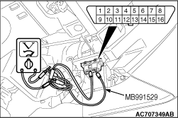
1.Den Diagnosecode-Prüfkabelsatz (MB991529) des Spezialwerkzeugs verwenden, um den ETACS-Anschluss (Anschluss 9) und die Masseanschlüsse (Anschlüsse 4 und 5) des Diagnosesteckers mit dem Voltmeter zu verbinden.2.Wenn der Zeiger des Voltmeters bei jeder Betätigung (ON/OFF) des jeweiligen Schalters einmal kurz ausschlägt, ist das Eingangssignal des Stromkreissystems dieses Schalters normal.
Englisches Original anzeigen
DIAGNOSIS FUNCTION
The diagnosis function retrieves diagnosis code and data list by M.U.T.-III and enables the performance of the actuator test.
Diagnosis code Data list output Actuator test Diagnosis deletion using M.U.T.-III Freeze frame data Status indication by diagnosis code ECU information display
note If a diagnosis code is set, the "status indication by diagnosis code" informs users whether a mechanical problem currently exists (current trouble) or whether it existed before but normal operation has been restored (past trouble).
HOW TO READ DIAGNOSIS CODE
caution Before connecting or disconnecting the M.U.T.-III, turn the ignition switch to the "LOCK" (OFF) position.
Connect the M.U.T.-III to the 16-pin diagnosis connector, and read the diagnosis code. note For details on how to use the M.U.T.-III, refer to the "M.U.T.-III Owner’s Manual." For the vehicles with security alarm sensor, when the M.U.T.-III is connected, if the ignition switch is turned to the "ON" position and the closed hood is opened, the security alarm siren sounds short. This short security alarm siren does not indicate malfunction. Therefore, ignore it and carry out diagnosis using M.U.T.-III. Ensure that the ignition switch is at the "LOCK" (OFF) position. Start up the personal computer. Connect special tool V.C.I.-Lite USB cable (MB992747/MB992748) or M.U.T.-III USB cable (MB991827) to V.C.I.-Lite (MB992744) or V.C.I. (MB991824) and the personal computer. Connect V.C.I.-Lite main harness A (MB992745) or M.U.T.-III main harness A (MB991910) to the V.C.I.-Lite or V.C.I. Connect the V.C.I.-Lite main harness A or M.U.T.-III main harness A to the diagnosis connector of the vehicle. note When the V.C.I.-Lite is connected to the diagnosis connector, the V.C.I.-Lite indicator lamp will be illuminated in a green colour. : Turn the V.C.I. power switch to the "ON" position. note When the V.C.I. is energised, the V.C.I. indicator lamp will be illuminated in a green colour. Start the M.U.T.-III system on the personal computer and turn the ignition switch to the "ON" position. Read the diagnosis code. note When storing the diagnosis code as reference information, the freeze frame data obtains the data when the diagnosis code is confirmed, and then stores the ECU status of that time. By analysing each data using M.U.T.-III, troubleshooting can be carried out efficiently. Disconnecting the M.U.T.-III is the reverse of the connecting sequence, making sure that the ignition switch is at the "LOCK" (OFF) position. note The ABS warning lamp may flash when the ignition switch is turned "ON" with the M.U.T.-III connected. This is because the diagnosis display function of the ABS warning lamp is activated by earthing the diagnosis connector terminal No.1, and is not detrimental in any way.
ERASING DIAGNOSIS CODE (BY USING THE M.U.T.-III)
caution Before connecting or disconnecting the M.U.T.-III, turn the ignition switch to the "LOCK" (OFF) position.
Connect the M.U.T.-III to the diagnosis connector, and erase the diagnosis code. The procedure is the same as "HOW TO READ DIAGNOSIS CODE".
ERASING DIAGNOSIS CODE (BY USING NO M.U.T.-III)
caution Some diagnosis codes can not be erased according to the procedure below. If you attempt to erase a diagnosis code, refer to an applicable GROUP.
1.Turn the ignition switch to the "LOCK" (OFF) position.
2.Disconnect the negative battery cable, wait for at least 10 minutes, and then reconnect it.
3.Start the engine and let it run at idle for 10 minutes.
HOW TO CONNECT THE SWS MONITOR
caution Special tool V.C.I.-Lite (MB992744) does not support the SWS monitor function. Use special tool V.C.I. (MB991824) when inspecting the SWS monitor function. Always turn the ignition switch to the "LOCK" (OFF) position before connecting or disconnecting the SWS monitor and the M.U.T.-III.
HOW TO CONNECT THE SWS COMMUNICATION LINE SPECIAL TOOL SWS MONITOR HARNESS (FOR COLUMN-ECU) MB991812
1.Remove the steering column cover.2.Remove the steering column switch connector.3.Connect special tool SWS monitor harness (for column-ECU) MB991812.
WHEN CONNECTING THE DIAGNOSIS CONNECTOR BY USING THE INTERMEDIATE WIRES FOR SWS MONITOR CUSTOMISATION
1.Connect the special tool Intermediate wires (MB991960) for SWS monitor customisation to the special tool M.U.T.-III main harness A (MB991910). 2.Connect the M.U.T.-III main harness A (with the intermediate wires) to the special tool V.C.I. (MB991824).3.Connect the intermediate wires for SWS monitor customisation to the diagnosis connector and the SWS monitor cartridge.
INPUT SIGNAL CHECK (WHEN USING THE M.U.T.-III) SWS
caution Special tool V.C.I.-Lite (MB992744) does not support the SWS monitor function. Use special tool V.C.I. (MB991824) when inspecting the SWS monitor function.
1.Connect the M.U.T.-III to the diagnosis connector, and erase the diagnosis code.2.If the M.U.T.-III buzzer sounds once when each switch is operated (ON/OFF), the input signal for that switch circuit system is normal.
INPUT SIGNAL CHECK (WHEN USING A VOLTMETER) SWS
1.Use the special tool diagnosis code check harness (MB991529) to connect the ETACS terminal (terminal 9) and the earth terminals (terminals 4 and 5) of the diagnosis connector to the voltmeter.2.If the needle of the voltmeter flickers once when each switch is operated (ON/OFF), the input signal for that switch circuit system is normal.
Passende Ersatzteile
Für fahrzeugspezifische Teilenummern zuerst ein Fahrzeug im Konto auswählen.
Passende Handbuchstellen
Keine passende Handbuchstelle gefunden.
Kommentare
Kommentare werden geladen …
Registrieren oder anmelden, um zu kommentieren