Einspritzpumpenbaugruppe
Fahrzeugdaten
AUS- UND EINBAU
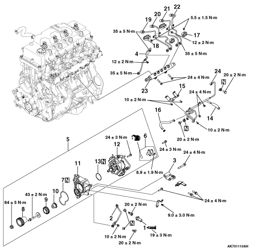
Ausbauschritte >>D>C>B>B>A>A>A>A>A>A>A>A>A>A>A
Ausbauschritte
- Öldruckschalter
- Ölleitungsbaugruppe
- Halterungsstrebe der Kraftstoffförderpumpe
- Rohrbaugruppe der Kraftstoffförderpumpe
- Kraftstoffförderpumpen- und Halterbaugruppe
- Satz Saugsteuerventil *1
- Dichtung des Kraftstoffförderpumpenhalters
- Zahnrad der Kraftstoffförderpumpe
- Zwischenrad-B-Baugruppe
- Zwischenradwelle A
- Halter der Kraftstoffförderpumpe
- Kraftstoffförderpumpen-Baugruppe
- O-Ring
- Kraftstoffrücklaufschlauch
- Kraftstoffleitungs-Halterung
- Kraftstoffrücklaufschlauch
- Einspritzleitungs-Klemme
- Klemme der Einspritzleitung
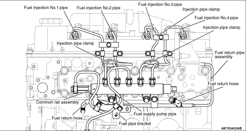
- Kraftstoffeinspritzleitung Nr. 1
- Kraftstoffeinspritzleitung Nr. 2
- Kraftstoffeinspritzleitung Nr. 3
- Kraftstoffeinspritzleitung Nr. 4
- Common-Rail-Baugruppe
- Kraftstoffrücklaufleitungs-Baugruppe
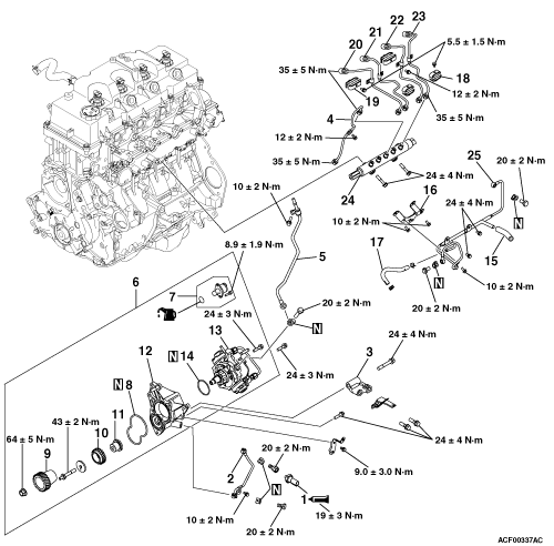

Ausbauschritte >>D>C>B>B>A>A>A>A>A>A>A>A>A>A>A
Ausbauschritte
- Öldruckschalter
- Ölleitungsbaugruppe
- Halterung der Kraftstoffförderpumpe
- Leitungsbaugruppe der Kraftstoffförderpumpe
- Kraftstoffeinspritz-Rücklaufleitungsbaugruppe
- Kraftstoffförderpumpen-Baugruppe und Halter
- Saugregelventilsatz *1
- Dichtung des Kraftstoffförderpumpenhalters
- Zahnrad der Kraftstoffförderpumpe
- Zwischenrad-B-Baugruppe
- Zwischenwelle A
- Halter der Kraftstoffförderpumpe
- Kraftstoffförderpumpen-Baugruppe
- O-Ring
- Kraftstoffrücklaufschlauch
- Kraftstoffleitungs-Halterung
- Kraftstoffrücklaufschlauch
- Einspritzleitungs-Schelle
- Einspritzleitungs-Schelle
- Kraftstoffeinspritzleitung Nr. 1
- Kraftstoffeinspritzleitung Nr. 2
- Kraftstoffeinspritzleitung Nr. 3
- Kraftstoffeinspritzleitung Nr. 4
- Common-Rail-Baugruppe
- Kraftstoffrücklaufleitungs-Baugruppe
AUSBAUHINWEISE
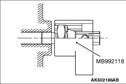
AUSBAU DES ÖLDRUCKSCHALTERS
Den Öldruckschalter mit dem Spezialwerkzeug Öldruckschalter-Steckschlüssel (MB992118) ausbauen.
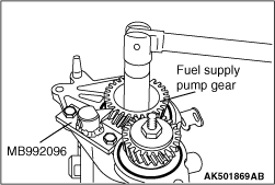
AUSBAU DER ZAHNRAD-/ZWISCHENRAD-B-BAUGRUPPE DER KRAFTSTOFFFÖRDERPUMPE
1. Das Zahnrad der Kraftstoffförderpumpe und das Zwischenrad B mit dem Spezialwerkzeug Zahnradhalter für Kraftstoffförderpumpe (MB992096) festhalten. 2. Die Mutter des Zahnrads der Kraftstoffförderpumpe und die Schraube des Zwischenrads B entfernen.
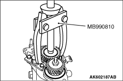
3. Das Zahnrad der Kraftstoffförderpumpe mit dem Spezialwerkzeug Seitenlagerabzieher (MB990810) ausbauen.
MONTAGEHINWEISE
1. Die Kraftstoffrücklaufleitungs-Baugruppe von Hand mit der Schraube leicht am Zylinderkopf befestigen.
2. Die Kraftstoffrücklaufleitungs-Baugruppe mit der Dichtung und der Hohlschraube am Zylinderkopf montieren und mit dem vorgeschriebenen Anzugsmoment festziehen. Anzugsmoment: 20 ± 2 N·m
3. Die Common-Rail-Baugruppe vorläufig am Zylinderkopf festziehen. Hinweis Dabei den Druckbegrenzer oder den Drucksensor des Common Rails nicht festhalten. Hinweis Vor dem Einbau sicherstellen, dass sich weder Fremdkörper noch Rost auf den Gewinden und der Dichtfläche einer Hochdruckleitung befinden.
4. Die Einspritzleitungsbaugruppen Nr. 1 bis Nr. 4 vorläufig mit den Muttern festziehen.
5. Die Schelle der Einspritzleitungen vorläufig mit den Schrauben festziehen.
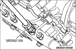
6. Die Einspritzleitungsbaugruppen Nr. 1 bis Nr. 4 mit dem Spezialwerkzeug „Einspritzleitungsschlüssel“ (MB992188) einbauen. Die Einspritzleitungsbaugruppen Nr. 1 bis Nr. 4 auf der Einspritzventilseite mit dem vorgeschriebenen Anzugsdrehmoment festziehen. Anzugsdrehmoment: 35 ± 5 N·m 7. Die Schelle der Einspritzleitungen mit dem vorgeschriebenen Anzugsdrehmoment festziehen. Anzugsdrehmoment: 5.5 ± 1.5 N·m
8. Die Einspritzleitungsbaugruppen Nr. 1 bis Nr. 4 mit dem Spezialwerkzeug „Einspritzleitungsschlüssel“ (MB992188) einbauen. Die Einspritzleitungsbaugruppen Nr. 1 bis Nr. 4 auf der Common-Rail-Seite mit dem vorgeschriebenen Anzugsdrehmoment festziehen. Anzugsdrehmoment: 35 ± 5 N·m Hinweis: Wenn die Gefahr einer Beschädigung besteht, Dichtband um die Kraftstoffleitung wickeln, um Schäden zu vermeiden. 9. Die Kraftstoffrücklaufleitungsbaugruppe mit der Dichtung und der Hohlschraube an der Common-Rail-Baugruppe montieren und mit dem vorgeschriebenen Anzugsdrehmoment festziehen. Anzugsdrehmoment: 20 ± 2 N·m 10. Die Common-Rail-Baugruppe mit dem vorgeschriebenen Anzugsdrehmoment festziehen. Anzugsdrehmoment: 24 ± 4 N·m 11. Die Einspritzleitung mit dem vorgeschriebenen Anzugsdrehmoment festziehen. Anzugsdrehmoment: 12 ± 2 N·m 12. Die Kraftstoffrücklaufleitungsbaugruppe mit dem vorgeschriebenen Anzugsdrehmoment festziehen. Anzugsdrehmoment: 24 ± 4 N·m 13. Den Kraftstoffrücklaufschlauch mit der Schlauchschelle an der Kraftstoffrücklaufleitungsbaugruppe montieren. 14. Den Halter der Kraftstoffleitung mit dem vorgeschriebenen Anzugsdrehmoment festziehen. Anzugsdrehmoment: 10 ± 2 N·m 15. Die Kraftstoffrücklaufleitungsbaugruppe mit dem vorgeschriebenen Anzugsdrehmoment festziehen. Anzugsdrehmoment: 10 ± 2 N·m
1. Das Zahnrad der Kraftstoffförderpumpe und das Zwischenrad B mit dem Spezialwerkzeug „Zahnradhalter der Kraftstoffförderpumpe“ (MB992096) festhalten. 2. Die Mutter des Zahnrads der Kraftstoffförderpumpe mit dem vorgeschriebenen Anzugsdrehmoment festziehen. Anzugsdrehmoment: 64 ± 5 N·m 3. Die Schraube des Zwischenrads B mit dem vorgeschriebenen Anzugsdrehmoment festziehen. Anzugsdrehmoment: 43 ± 2 N·m
1. Die Kurbelwelle im Uhrzeigersinn drehen, um Zylinder Nr. 1 in die Stellung des oberen Totpunkts zu bringen.
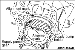
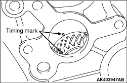
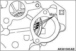
2. Die Frontplatte einbauen, nachdem die Markierungen am Zahnrad der Kraftstoffförderpumpe und am Halter der Kraftstoffförderpumpe ausgerichtet wurden, sodass das Zahnrad der Kraftstoffförderpumpe nicht gedreht werden kann. Die Frontplatte so einbauen, dass sich das Zahnrad der Kraftstoffförderpumpe nicht mitdreht und die Passmarkierungen des Zahnrads der Kraftstoffförderpumpe und des Halters der Kraftstoffförderpumpe übereinstimmen.
3. Auf den Zahnrädern mit der Ausrichtmarkierung des Zahnrads der Kraftstoffförderpumpe ist weiße Farbe aufgetragen. Sicherstellen, dass die weiße Farbmarkierung am Zahnrad der Kraftstoffförderpumpe mit der Ausrichtmarkierung der Frontplatte übereinstimmt. Hinweis: Von vorn betrachtet ist die Ausrichtmarkierung am Zahnrad der Kraftstoffförderpumpe gegenüber der Ausrichtmarkierung an der Frontplatte um etwa 1 - 2 Zähne versetzt. Hinweis: Sicherstellen, dass die drei Markierungen des Zahnrads der Kraftstoffförderpumpe durch die Einbauöffnung der Servolenkungspumpe sichtbar sind.
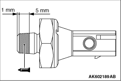
1. Vorsicht Darauf achten, dass der Ölkanal nicht durch Dichtmittel verstopft wird. Bei Wiederverwendung des Sensors das vorgeschriebene Dichtmittel auf das Gewinde auftragen. Vorgeschriebenes Dichtmittel: Three bond 1215, Three bond 1212D oder ein genau gleichwertiges Produkt
2. Den Motoröldruckschalter zusammen mit der Ölfilterhalterung unter Verwendung des Spezialwerkzeugs Steckschlüssel für Öldruckschalter (MB992118) mit dem vorgeschriebenen Anzugsdrehmoment festziehen. Anzugsdrehmoment: 19 ± 3 N·m
Englisches Original anzeigen
INJECTION PUMP ASSEMBLY
REMOVAL AND INSTALLATION
Removal steps >>D>C>B>B>A>A>A>A>A>A>A>A>A>A>A
Removal steps
- Oil pressure switch
- Oil pipe assembly
- Fuel supply pump holder bracket
- Fuel supply pump pipe assembly
- Fuel supply pump assembly and holder
- Suction control valve kit *1
- Fuel supply pump holder gasket
- Fuel supply pump gear
- Idler gear B assembly
- Idler shaft A
- Fuel supply pump holder
- Fuel supply pump assembly
- O-ring
- Fuel return hose
- Fuel pipe bracket
- Fuel return hose
- Injection pipe clamp
- Injection pipe clamp
- Fuel injection pipe No.1
- Fuel injection pipe No.2
- Fuel injection pipe No.3
- Fuel injection pipe No.4
- Common rail assembly
- Fuel return pipe assembly
Removal steps >>D>C>B>B>A>A>A>A>A>A>A>A>A>A>A
Removal steps
- Oil pressure switch
- Oil pipe assembly
- Fuel supply pump holder bracket
- Fuel supply pump pipe assembly
- Fuel injection exhaust pipe assembly
- Fuel supply pump assembly and holder
- Suction control valve kit *1
- Fuel supply pump holder gasket
- Fuel supply pump gear
- Idler gear B assembly
- Idler shaft A
- Fuel supply pump holder
- Fuel supply pump assembly
- O-ring
- Fuel return hose
- Fuel pipe bracket
- Fuel return hose
- Injection pipe clamp
- Injection pipe clamp
- Fuel injection pipe No.1
- Fuel injection pipe No.2
- Fuel injection pipe No.3
- Fuel injection pipe No.4
- Common rail assembly
- Fuel return pipe assembly
REMOVAL SERVICE POINTS
OIL PRESSURE SWITCH REMOVAL
Using special tool Oil pressure switch socket wrench (MB992118), removal the oil pressure switch.
FUEL SUPPLY PUMP GEAR/IDLER GEAR B ASSEMBLY REMOVAL
1.Using the special tool Supply pump gear stopper (MB992096), hold the fuel supply pump gear and idler gear B.2.Remove the hold the fuel supply pump gear nut and idler gear B bolt.
3.Using the special tool Side bearing puller (MB990810), remove the fuel supply pump gear.
INSTALLATION SERVICE POINTS
caution The reinstallation histories of the removed injection pipe and supply pump pipe are up to five times. To count how many times the injection pipe and supply pump is reinstalled, record the number of the reinstallation histories on the service booklet by adding this latest number of the histories, which is usually "1," to the previous one. Use a new injection pipe and supply pump when the total reinstallation history numbers reach five times, or when the supply pump or common rail is replaced. In this case, record "a new injection pipe and supply pump, the number of the reinstallation histories is zero" on the service booklet. If a fuel leak is present in the fuel injection pipe and fuel injection pipe set once, do not reuse it and replace with a new one. If the fuel injector assembly, common rail assembly or supply pump assembly is replaced, the contact surface (seal surface) between the fuel injection pipe and fuel injection pipe set, and the other side component is changed, do not reuse the fuel injection pipe and fuel supply pump pipe and replace with a new one. When the injection pipe and supply pump is reinstalled, confirm there is no foreign material on the seal surface or in the pipe and then install it not to deviate from the axis, fitting the seal surface.
1.Install the fuel return pipe assembly lightly with bolt onto the cylinder head by hand.
2.Install fuel return pipe assembly to the cylinder head with gasket, eye bolt to the specified torque.Tightening torque: 20 ± 2 N·m
3.A temporary tightening makes common rail assembly cylinder head. note At this time, do not hold the pressure limiter or pressure sensor of the common rail. note Before the installation, confirm there is neither foreign material nor a rust on the threads and the sealing surface of a high-pressure pipe.
4.Temporarily tighten the fuel injection pipe assembly No.1 to No.4 with nuts.
5.Temporarily tighten the fuel injection pipe clamp with bolts.
6.Using special tool Fuel injection pipe wrench (MB992188), install injection pipe assembly No.1 to No.4.Tighten the fuel injection pipe assembly No.1 to No.4 to the specified torque at injector side.Tightening torque: 35 ± 5 N·m7.Tighten the injection pipe clamp to the specified torque.Tightening torque: 5.5 ± 1.5 N·m
8.Using special tool Fuel injection pipe wrench (MB992188), install injection pipe assembly No.1 to No.4.Tighten the fuel injection pipe assembly No.1 to No.4 to the specified torque at common rail side.Tightening torque: 35 ± 5 N·m note When there is a fear that a bruise is put, wind sealing tape around the fuel pipe, to prevent damage. 9.Install fuel return pipe assembly to the common rail assembly with gasket, eye bolt to the specified torque.Tightening torque: 20 ± 2 N·m10.Tighten the common rail assembly to the specified torque.Tightening torque: 24 ± 4 N·m11.Tighten the fuel injection pipe to the specified torque.Tightening torque: 12 ± 2 N·m12.Tighten the fuel return pipe assembly to the specified torque.Tightening torque: 24 ± 4 N·m13.Install fuel return hose to the fuel return pipe assembly with hose clip.14.Tighten the fuel pipe bracket to the specified torque.Tightening torque: 10 ± 2 N·m15.Tighten the fuel return pipe assembly to the specified torque.Tightening torque: 10 ± 2 N·m
1.Using the special tool Supply pump gear stopper (MB992096), hold the fuel supply pump gear and idler gear B.2.Torque the fuel supply pump gear nut to the specified torque.Tightening torque: 64 ± 5 N·m3.Torque the idler gear B bolt to the specified torque.Tightening torque: 43 ± 2 N·m
1.Turn the crankshaft clockwise to bring No. 1 cylinder to the top dead centre position.
2.Install the front plate after aligning the marks on the fuel supply pump gear and the fuel supply pump holder so that the fuel supply gear cannot be rotated.It’s installed in front plate so that fuel supply pump gear doesn’t revolve together with a match mark of fuel supply pump gear and fuel supply pump holder.
3.A white paint is applied to the gears having the alignment mark of the fuel supply pump gear. Confirm the white paint on the fuel supply pump gear is aligned with the alignment mark of the front plate. note When viewed from the front, the alignment mark on the fuel supply pump gear deviates from that on the front plate by about 1 - 2 gears. note Confirm three marks of the supply pump gear are visible from the installation hole of the power steering pump.
1. caution Be careful not to block the oil passage with sealant. When reusing the sensor, apply the specified sealant to the threads.Specified sealant:Three bond 1215, Three bond 1212D or exact equivalent
2.Tighten the engine oil pressure switch together with the oil filter bracket to the specified torque, using special tool Oil pressure switch socket wrench (MB992118).Tightening torque: 19 ± 3 N·m
Passende Ersatzteile
Für fahrzeugspezifische Teilenummern zuerst ein Fahrzeug im Konto auswählen.
Passende Handbuchstellen
Keine passende Handbuchstelle gefunden.
Kommentare
Kommentare werden geladen …
Registrieren oder anmelden, um zu kommentieren