Ölwanne und Ölsieb
Fahrzeugdaten
AUS- UND EINBAU
Arbeiten vor dem Ausbau Motoröl ablassen (siehe GRUPPE 12 - Wartung am Fahrzeug, Motorölwechsel). Vorderachsdifferenzialträger-Baugruppe ausbauen (siehe GRUPPE 26 - Differenzialträger- und Freilaufkupplungs-Baugruppe).
Arbeiten nach dem Einbau Vorderachsdifferenzialträger-Baugruppe einbauen (siehe GRUPPE 26 - Differenzialträger und Freilaufkupplung). Motoröl auffüllen (siehe GRUPPE 12 - Wartung am Fahrzeug, Motorölwechsel).
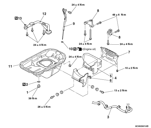
Ausbauschritte 1. Ablassschraube der Motorölwanne >>B>A
Ausbauschritte
- Ablassschraube der Motorölwanne
- Dichtung der Ablassschraube der Motorölwanne
- Batteriekabelanschluss
- Motorölwannenabdeckungs-Baugruppe (L.H.)
- Isolator
- Motorölwannenabdeckungs-Baugruppe
- Staubschutzabdeckung
- Versteifung
- Motorölmessstab- und Führungs-Baugruppe
- O-Ring
- Motorölwanne
- Motorölwannensieb
- O-Ring
HINWEIS ZUM AUSBAU
AUSBAU DER MOTORÖLWANNE
1.Die Befestigungsschrauben der Motorölwanne entfernen.
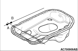
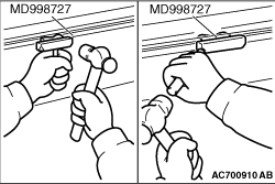
2. Vorsicht Den Ölwannen-FIPG-Schneider (MD998727) nicht im Bereich A der Motorölwanne verwenden. Die Verwendung des Spezialwerkzeugs (MD998727) im Bereich A kann zu einer Verformung des vorderen Gehäuses führen, da das vordere Gehäuse aus Aluminium besteht. Das Spezialwerkzeug (MD998727) im Bereich B zwischen Zylinderblock und Motorölwanne einschlagen und anschließend das Spezialwerkzeug (MD998727) seitlich verschieben. Hinweis Wenn umliegende Teile den Ausbau behindern, muss das Spezialwerkzeug (MD998727) nicht verwendet werden. 3. Nachdem die Motorölwanne vom Zylinderblock getrennt wurde, die Befestigungsschrauben des Motorölwannensiebs entfernen und anschließend die Motorölwanne zusammen mit dem Motorölwannensieb ausbauen.
HINWEISE ZUM EINBAU
1. Die Anlageflächen von Motorölwanne, Steuergehäuse-Baugruppe, Frontplatten-Baugruppe und Kurbelgehäuse-Baugruppe mit einem Schaber oder einer Drahtbürste reinigen.
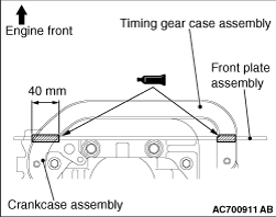
2. Das vorgeschriebene Dichtmittel auf die Anlagefläche der Frontplatten-Baugruppe und der Motorölwanne auftragen. Vorgeschriebenes Dichtmittel: ThreeBond 1207F Hinweis Die Motorölwanne unmittelbar nach dem Auftragen des Dichtmittels einbauen.
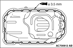
3. Das vorgeschriebene Dichtmittel wie abgebildet auf die Anlagefläche der Motorölwanne auftragen. Vorgeschriebenes Dichtmittel: ThreeBond 1207F Hinweis Die Motorölwanne unmittelbar nach dem Auftragen des Dichtmittels einbauen. 4. Die Motorölwanne an der Kurbelgehäuse-Baugruppe anbringen. 5. Vorsicht Nach dem Einbau bis zum Ablauf einer ausreichenden Zeitspanne (eine Stunde oder länger) weder Öl noch Wasser auf den Dichtmittel-Auftragsbereich gelangen lassen und den Motor nicht starten. Die Schrauben der Motorölwanne mit dem vorgeschriebenen Anzugsdrehmoment festziehen. Anzugsdrehmoment: 24 ± 4 N·m
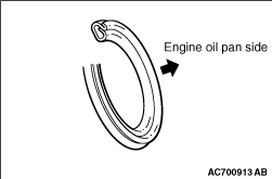
Die Dichtung durch eine neue Dichtung ersetzen. Die neue Dichtung in der in der Abbildung gezeigten Ausrichtung einbauen.
Englisches Original anzeigen
OIL PAN AND OIL STRAINER
REMOVAL AND INSTALLATION
Pre-removal Operation Engine Oil Draining (Refer to GROUP 12 - On-vehicle Service, Engine Oil Replacement ). Front Differential Carrier Assembly Removal (Refer to GROUP 26 - Differential Carrier and Free Wheeling Clutch Assembly ).
Post-installation Operation Front Differential Carrier Assembly Installation (Refer to GROUP 26 - Differential Carrier and Free Wheeling Clutch ). Engine Oil Refilling (Refer to GROUP 12 - On-vehicle Service, Engine Oil Replacement ).
Removal steps 1. Engine oil pan drain plug >>B>A
Removal steps
- Engine oil pan drain plug
- Engine oil pan drain plug gasket
- Battery cable connection
- Engine oil pan cover assembly (L.H.)
- Insulator
- Engine oil pan cover assembly
- Dust cover
- Stiffener
- Engine oil level gauge and guide assembly
- O-ring
- Engine oil pan
- Engine oil pan strainer
- O-ring
REMOVAL SERVICE POINT
ENGINE OIL PAN REMOVAL
1.Remove the engine oil pan mounting bolts.
2. caution Do not use special tool oil pan FIPG cutter (MD998727) in area A of the engine oil pan. Using the special tool (MD998727) in area A may cause deformation of the front case because the front case is made of aluminium. Tap the special tool (MD998727) into the range B between the cylinder block and the engine oil pan, and then slide the special tool (MD998727) sideways. note If any surrounding parts interfere with the removal, there is no need to use the special tool (MD998727). 3.With the engine oil pan separated from the cylinder block, remove the engine oil pan strainer mounting bolts, and then remove the engine oil pan together with engine oil pan strainer.
INSTALLATION SERVICE POINTS
1.Clean the engine oil pan, timing gear case assembly, front plate assembly and crankcase assembly matching surfaces with a scraper or a wire brush.
2.Apply the specified sealant to the matching surface of the front plate assembly and engine oil pan.Specified sealant: ThreeBond 1207F note Install the engine oil pan immediately after applying sealant.
3.Apply the specified sealant to the engine oil pan matching surface as shown.Specified sealant: ThreeBond 1207F note Install the engine oil pan immediately after applying sealant. 4.Install the engine oil pan to the crankcase assembly.5. caution After the installation, until a sufficient period of time (one hour or more) elapses, do not apply the oil or water to the sealant application area or start the engine. Tighten the engine oil pan bolts to the specified torque.Tightening torque: 24 ± 4 N·m
Replace the gasket with a new gasket. Install the new gasket in the direction shown in the illustration.
Passende Stelle im V60-Handbuch
Passende Ersatzteile
Für fahrzeugspezifische Teilenummern zuerst ein Fahrzeug im Konto auswählen.
Passende Handbuchstellen
Keine passende Handbuchstelle gefunden.
Kommentare
Kommentare werden geladen …
Registrieren oder anmelden, um zu kommentieren